

 русский
  Español
  عربى
عربى 


What Does a Brake Chamber Do? A Guide to Air & Disc Brake Chambers
Content
- 1 What Does a Brake Chamber Do?
- 2 How a Brake Chamber Works Step by Step
- 3 Key Components Inside a Brake Chamber
- 4 What Is a Disc Brake Chamber and How Is It Different?
- 5 Common Brake Chamber Sizes and Type Numbers
- 6 Signs of a Failing Brake Chamber
- 7 Inspection and Maintenance Guidelines
- 8 Replacement Considerations and Safety Notes
- 9 How Chamber Size Affects Braking Force
- 10 Frequently Asked Questions
- 11 References
What Does a Brake Chamber Do?
A brake chamber converts compressed air pressure into mechanical push-rod force that physically applies a vehicle's brakes. When the driver presses the brake pedal, air pressure enters the chamber and pushes a flexible diaphragm against a push rod, which extends outward and activates the brake mechanism — either an S-cam and brake shoes on a drum brake, or a caliper lever on a disc brake. Without a functioning brake chamber, air pressure has no way to translate into the clamping or friction force needed to slow or stop the vehicle.
On most heavy trucks, trailers, and buses, brake chambers operate within an air pressure range of roughly 60 to 100 psi, with the system typically maintaining 100 to 120 psi in the air reservoirs to ensure a safety margin. A single combination chamber usually houses two separate functions in one housing: a service brake section that applies the brakes during normal driving, and a spring brake section that automatically applies the parking or emergency brake if air pressure drops too low. This dual design is what allows air brake systems to "fail safe" — losing air pressure causes the brakes to engage rather than release.
How a Brake Chamber Works Step by Step
Understanding the internal sequence helps explain why brake chambers are considered one of the most safety-critical components on an air-braked vehicle.
Service Brake Application
When the driver presses the brake pedal, the foot (treadle) valve releases compressed air into the service brake side of the chamber. Air pressure pushes against a rubber diaphragm, forcing the push rod to extend. The push rod connects to a slack adjuster or caliper lever, rotating the S-cam or squeezing the caliper, which presses the brake shoes or pads against the drum or rotor.
Spring Brake (Parking Brake) Application
The rear section of a combination chamber contains a powerful coil spring that is held compressed by air pressure during normal driving. When the parking brake is set or air pressure drops below approximately 20 to 45 psi, the spring is released and forces its own push rod outward, mechanically applying the brakes even with zero air in the system. This is why a vehicle with a major air leak will eventually stop on its own rather than roll freely.
Brake Release
Releasing the brake pedal allows air to exhaust from the service chamber through the treadle valve. A return spring inside the chamber then pulls the push rod back to its resting position, releasing pressure on the brake mechanism so the wheel can rotate freely again.
Key Components Inside a Brake Chamber
Although designs vary slightly between manufacturers, nearly every air brake chamber shares the same core internal parts.
| Component | Function |
|---|---|
| Diaphragm | Flexible rubber membrane that air pressure pushes against to move the push rod |
| Push Rod | Steel rod that transfers diaphragm force to the slack adjuster or caliper lever |
| Return Spring | Pulls the push rod back to its resting position once air is released |
| Pressure Housing | Sealed metal shell that receives compressed air from the brake line |
| Clamp Ring | Bolts the two housing halves together and seals the diaphragm in place |
| Power Spring (Spring Brake Models) | Large coil spring that mechanically applies the parking/emergency brake when air pressure is removed |
What Is a Disc Brake Chamber and How Is It Different?
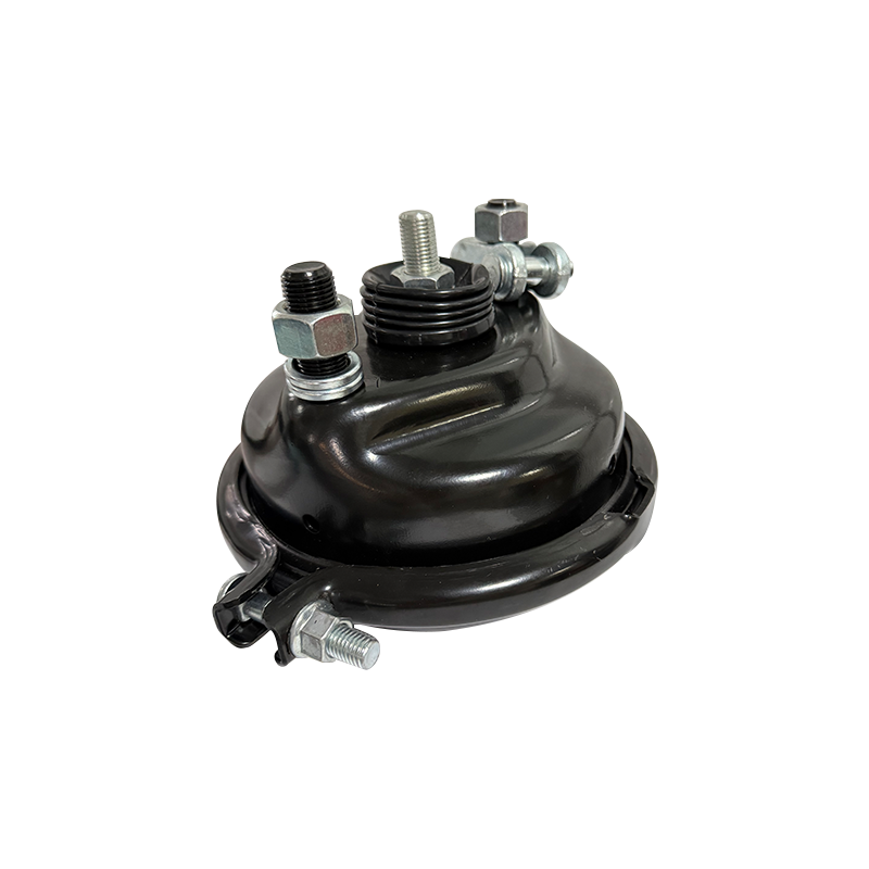
A disc brake chamber is an air brake actuator specifically designed and mounted to work with an air disc brake (ADB) caliper rather than a drum brake's S-cam and shoe assembly. While the basic air-to-mechanical conversion principle is identical, several practical differences set disc brake chambers apart.
Shorter Stroke Length
Air disc brake calipers include an internal automatic adjuster that continuously maintains a very small, consistent running clearance between the pad and rotor — typically around 0.4 to 0.6 mm. Because of this, disc brake chambers generally use a standard stroke of about 2.0 inches, compared with the 2.5-inch long-stroke chambers commonly required on drum brakes to compensate for shoe wear between adjustments.
Direct Caliper Mounting
Rather than connecting through an external slack adjuster and S-cam shaft, a disc brake chamber typically bolts directly onto the caliper housing and acts on an internal lever that drives a bridge or power screw mechanism, squeezing the pads onto the rotor from both sides.
Faster, More Consistent Response
Because there is no slack to take up before the pads contact the rotor, disc brake chambers tend to produce a more immediate and consistent brake response across the chamber's service life, whereas drum brake response can vary slightly as the slack adjuster compensates for shoe wear over time.
Comparison Table: Disc Brake Chamber vs Drum Brake (S-Cam) Chamber
| Feature | Disc Brake Chamber | Drum Brake (S-Cam) Chamber |
|---|---|---|
| Typical Stroke | ~2.0 in (standard stroke) | ~2.5 in (long stroke) |
| Mounting | Bolted directly to caliper | Mounted to spider, linked via slack adjuster |
| Adjustment Mechanism | Internal automatic caliper adjuster | External automatic slack adjuster |
| Response Consistency | Very consistent over time | Can vary slightly with shoe wear |
Common Brake Chamber Sizes and Type Numbers
Brake chambers are identified by a "Type" number that corresponds to the diaphragm's effective surface area in square inches — not its physical outer diameter. A larger Type number produces more output force at the same air pressure, which is why heavier axle positions typically use larger chambers.
| Chamber Type | Effective Area | Typical Application |
|---|---|---|
| Type 9 | 9 sq in | Light steer axles |
| Type 12 | 12 sq in | Steer axles, light trailers |
| Type 16 | 16 sq in | Mid-weight drive and trailer axles |
| Type 20 / 24 | 20-24 sq in | Standard drive axles and disc brake calipers |
| Type 30 | 30 sq in | Heavy drive axles, common spring brake size |
Most modern air disc brake chambers fall in the Type 20 to Type 24 range, which provides enough clamping force for the caliper while keeping the chamber compact enough to fit the tighter mounting envelope around a disc brake assembly.
Signs of a Failing Brake Chamber
Brake chambers are exposed to constant pressure cycling, road debris, moisture, and temperature swings, so wear is inevitable over the life of a vehicle. Watch for these warning signs:
- Visible air leaks or a hissing sound coming from the chamber housing or clamp ring.
- Slow brake application or release, suggesting a damaged diaphragm or restricted air passage.
- Push rod travel that exceeds the manufacturer's specified limit, often 2 to 2.5 inches depending on chamber type.
- Visible rust, corrosion, or cracking on the housing, particularly around the clamp ring seam.
- A parking brake that fails to hold the vehicle on a grade, indicating a weak or broken power spring.
- Uneven brake wear or pulling to one side under braking, which can point to one chamber underperforming relative to the others.
A ruptured diaphragm is one of the most common failure points and typically causes an immediate, noticeable drop in air pressure along with a complete loss of braking force at that wheel position — making it a priority repair rather than something to defer. Fleet maintenance records consistently show diaphragm rupture and clamp ring corrosion as the two leading causes of unscheduled brake chamber replacement.
Inspection and Maintenance Guidelines
Because brake chambers are classified as safety-critical components, most fleets follow a structured inspection schedule rather than waiting for visible failure.
Push Rod Travel Check
Technicians measure how far the push rod extends when the brakes are fully applied at around 90 to 100 psi. Excessive travel beyond the chamber's rated stroke usually indicates a worn slack adjuster, an out-of-adjustment brake, or internal chamber wear, and is one of the most common items flagged during a Commercial Vehicle Safety Alliance (CVSA) roadside inspection.
Leak Testing
A soap-and-water solution applied around the clamp ring and air line fittings will bubble visibly if air is escaping. Many fleets also perform a static air-loss test, watching for system pressure to hold steady over a set time with the brakes applied and the engine off.
Recommended Inspection Frequency
Most maintenance programs recommend a full brake chamber inspection at every preventive maintenance (PM) interval, typically every 25,000 to 30,000 miles for over-the-road trucks, with a visual check during every pre-trip inspection.
Replacement Considerations and Safety Notes
Replacing a brake chamber — especially a spring brake (parking brake) chamber — requires specific precautions because of the stored mechanical energy inside the power spring.
- Always cage the spring brake using the chamber's built-in caging bolt before disconnecting it, since the compressed power spring can release with enough force to cause serious injury.
- Match the replacement chamber's Type number and stroke length exactly to the original specification for that axle position.
- Inspect and, if needed, replace the mounting bracket and clamp band, since corrosion in these areas is a common cause of repeat failures.
- After installation, perform a full push rod travel check and leak test before returning the vehicle to service.
- Never attempt to disassemble a spring brake chamber section in the field; these are designed to be replaced as a sealed unit due to the danger posed by the internal spring.
Most OEM and aftermanufacturer brake chambers carry a service life expectation of roughly 5 to 7 years or 250,000 to 500,000 miles under normal operating conditions, though harsh climates, road salt exposure, and frequent stop-and-go duty cycles can shorten that interval considerably.
How Chamber Size Affects Braking Force
The basic physics behind a brake chamber is straightforward: output force equals air pressure multiplied by the diaphragm's effective area. This relationship explains why selecting the correct Type number for each axle position is just as important as the chamber's mechanical condition.
For example, a Type 30 chamber at 100 psi can theoretically generate around 3,000 pounds of initial push-rod force (30 square inches x 100 psi), while a smaller Type 12 chamber under the same pressure produces only about 1,200 pounds. In practice, the usable force is lower than this theoretical figure because the internal return spring and diaphragm geometry absorb some of that force as the push rod extends through its stroke, but the relative difference between chamber sizes remains proportional.
This is also why undersized or mismatched chambers are a safety concern: installing a smaller chamber than specified for a given axle can leave the brake unable to generate adequate clamping force at the rotor or drum, even though the chamber itself appears to be functioning normally. Conversely, an oversized chamber may apply more force than the caliper or foundation brake hardware was designed to handle, accelerating wear on pads, rotors, or brake shoes.
Frequently Asked Questions
Can a disc brake chamber be used on a drum brake system, or vice versa?
Generally no. Although both chamber types use the same air-to-mechanical principle, the stroke length, mounting bolt pattern, and lever geometry are matched to the specific brake design, so swapping between disc and drum applications without manufacturer approval can result in inadequate stroke or improper clamping force.
Why do spring brake chambers look bigger than service-only chambers?
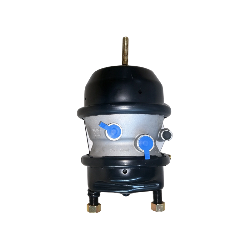
A combination spring brake chamber houses two sections in one unit — the service diaphragm chamber and the larger spring brake section behind it — so the overall housing is longer than a service-only chamber to accommodate the power spring needed for parking and emergency braking.
What happens if a brake chamber fails completely while driving?
A single chamber failure typically results in reduced braking force at that wheel position rather than total brake loss, since most heavy vehicles have multiple independently operating brake chambers across different axles. However, it significantly increases stopping distance and should be treated as an immediate out-of-service condition.
References
- Federal Motor Carrier Safety Administration (FMCSA) - Commercial vehicle brake system inspection standards
- Commercial Vehicle Safety Alliance (CVSA) - North American Standard Out-of-Service Criteria for brake systems
- SAE International - Air brake actuator design and performance standards
- National Highway Traffic Safety Administration (NHTSA) - Federal Motor Vehicle Safety Standard 121 (Air Brake Systems)
Recommended Products



-
When a driver presses the brake pedal on a commercial truck or trailer, a sequence of events begins ...
-
QUICK ANSWER A disc brake chamber converts compressed air pressure into the mechanical force that ...
-
A brake chamber is caged by threading the manual caging bolt through the chamber's push rod housing...
-
If you are qualifying a wedge brake chamber factory, settle five things before you talk about price...
-
A fleet running 40-ton tractors can feel the difference between two nominally identical S-cam brake...
-
A purchasing manager once dismissed a low-priced ADB brake chamber factory because its sample faile...

- WHY US
- Company Profile
- Certifications
- News
- PRODUCTS
- S-Cam Type Brake Chamber
- DISC Brake Chamber
- Wedge Brake Chamber
- Piggyback Brake Chamber
- Brake Chamber Repair Kits
- MANUFACTURING
- Customer Service
- Factory Tour
-
-
No.90 Zhancheng Avenue, Zhuji City, Zhejiang Province, China

-
rongzhan@zjrongzhan.com / judith@zjrongzhan.com

-
+86-15258814607

-
- CONTACT


