

 русский
  Español
  عربى
عربى 


How Does a Brake Chamber Ensure Commercial Safety
Content
- 1 The Role of Brake Chamber in Commercial Vehicle Safety
- 2 Classifications and Technical Specifications of Brake Chambers
- 3 Deep Dive into the Type 30/30 Brake Chamber: Industry Standard
- 4 Application-Specific Engineering: Semi Trucks and Trailers
- 5 Industrial Manufacturing Excellence and Quality Assurance
- 6 Brake Chamber Technical FAQ & Procurement Insights
- 6.1 Q1: What is the main structural and operational difference between a Type 30/30 brake chamber and a Type 24/30 configuration?
- 6.2 Q2: How does a long stroke brake chamber reduce fleet maintenance costs compared to a standard short stroke brake chamber?
- 6.3 Q3: Can an air disk brake chamber be retrofitted onto a traditional drum-brake trailer brake chamber bracket?
- 6.4 Q4: What are the critical signs that a semi truck brake chamber diaphragm requires immediate replacement?
- 6.5 Q5: Why is the tensile strength and quality of the return spring within a spring brake chamber vital for vehicle safety?
- 7 References
The Role of Brake Chamber in Commercial Vehicle Safety
In heavy-duty commercial transportation, pneumatic braking systems serve as the primary line of defense against catastrophic mechanical failures. At the core of this system is the brake chamber, a specialized precision engineering component designed to execute mechanical clamping force under rigorous operating conditions. Operating on compressed air, the air brake chamber acts as the vital actuator that converts fluid energy into predictable linear force, ensuring that heavy-duty vehicles can decelerate safely under maximum payload capacities.
Understanding the Brake Chamber Mechanism
The primary function of an air brake chamber is the conversion of pneumatic energy. When the operator depresses the brake pedal, compressed air enters the chamber housing through dedicated inlet ports, exerting uniform pressure across a heavy-duty synthetic rubber diaphragm. This air pressure forces the diaphragm forward, shifting an internal pushrod assembly outward. The linear travel of the pushrod engages the slack adjuster, which rotates the brake camshaft and forces the brake linings firmly against the drum or disc surface.
To provide a clear understanding of the mechanical thresholds within standard pneumatic systems, the table below outlines the core operational parameters governing standard air brake chamber configurations:
| Operational Metric | Standard Performance Threshold | Technical Significance |
|---|---|---|
| Maximum Working Pressure | 1.0 MPa (150 PSI) | Ensures structural integrity during emergency braking sequences without housing deformation. |
| Standard Operating Pressure | 0.65 - 0.80 MPa (95 - 115 PSI) | The nominal pressure range managed by the vehicle's air compressor and governor system. |
| Ambient Temperature Range | -40°C to +80°C | Guarantees rubber diaphragm elasticity and sealing efficiency under extreme geographical environments. |
| Pushrod Stroke Range | 50.8 mm - 76.2 mm (2.0 - 3.0 Inches) | Determines the mechanical clearance compensation available before brake fade occurs. |
Once air pressure is released from the air brake chamber, an internal heavy-duty return spring instantly forces the pushrod back to its baseline position. This rapid mechanical reset prevents brake drag, minimizes parasitic thermal build-up, and protects the friction linings from premature wear during continuous long-haul transit cycles.
Why Procurement Managers Prioritize OEM-Quality Truck Brake Chambers
For technical directors and fleet procurement managers managing international supply chains, selecting a truck brake chamber extends beyond baseline pricing metrics. It is a critical decision focused on operational uptime, component longevity, and stringent risk mitigation. High-grade truck brake chambers must deliver unyielding reliability across millions of operational cycles to ensure continuous compliance with rigorous global safety standards, including FMVSS 121 in North America and SAE J1469 mechanical protocols.
Inferior manufacturing processes often lead to micro-leakage at the housing clamp bands or premature fatigue failure in the internal return springs. A minor pressure drop within a single truck brake chamber can disrupt the pneumatic balance of the entire vehicle, resulting in uneven braking force, increased stopping distances, and localized overheating on specific axles. By prioritizing standardized technical parameters, specialized materials, and verified fatigue lifecycles, global sourcing specialists protect their equipment investments and eliminate the costly maintenance overhead associated with premature component failure in the field.
Classifications and Technical Specifications of Brake Chambers
Pneumatic braking systems rely on specific configurations of mechanical actuators to manage different operational demands, including service braking, emergency backup, and parking stability. Understanding the precise engineering distinctions between these configurations ensures proper axle weight distribution, appropriate thermal management, and reliable mechanical force output across commercial fleets.
Service Brake Chambers vs. Spring Brake Chambers
The fundamental classification of an air brake chamber rests on its dual or single functional design. A service brake chamber is a single-compartment unit utilized exclusively for active deceleration. It contains a single diaphragm and pushrod assembly, converting pneumatic force only when the operator applies pressure to the foot valve. These are typically deployed on front steering axles where parking locks are not mechanically required.
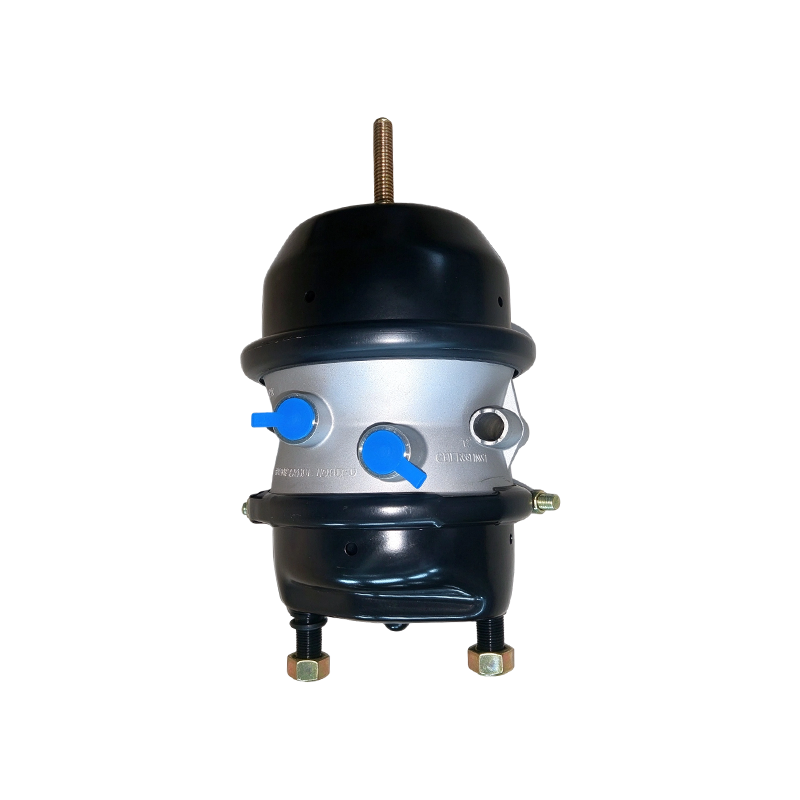
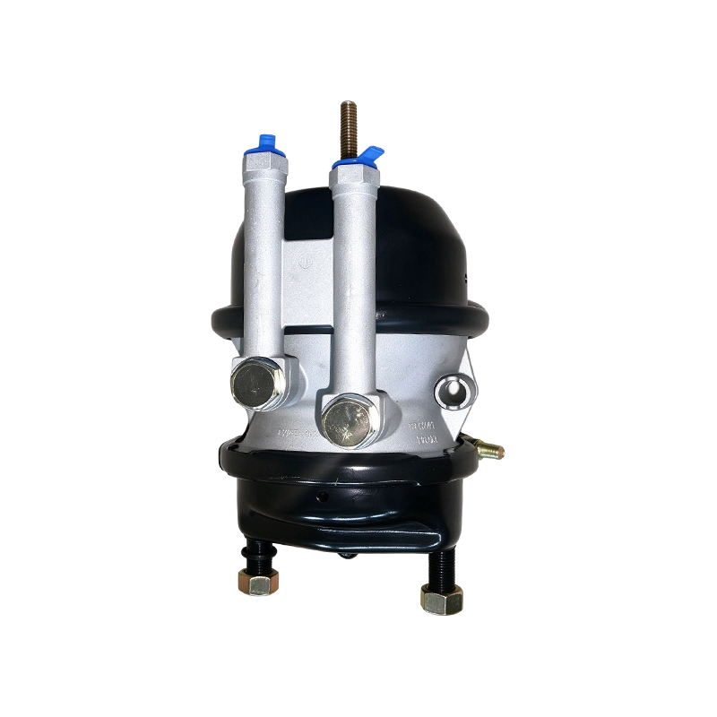
In contrast, a spring brake chamber is a dual-compartment component that integrates both service braking and emergency/parking capabilities into a single tandem housing. The primary section operates identically to a standard service unit. The secondary section contains a high-tension steel power spring held under compression by constant system air pressure. If pneumatic system pressure drops below safety thresholds (e.g., due to a broken airline), the compressed air holding back the spring vents, allowing the mechanical force of the power spring to expand instantly and lock the brakes. This dual-action mechanism makes the spring brake chamber the global standard for rear drive axles and heavy-duty trailer applications.
| Technical Attribute | Service Brake Chamber | Spring Brake Chamber |
|---|---|---|
| Housing Configuration | Single-diaphragm compartment | Tandem double-diaphragm / Dual-compartment |
| Primary Functional Role | Active service deceleration only | Service braking + Mechanical parking + Failsafe emergency lock |
| Actuation Source | Controlled pneumatic application | Pneumatic pressure (Service) / Mechanical spring force (Parking) |
| Common Axle Placement | Front steering axles | Rear drive axles and trailer axles |
Standard Stroke vs. Long Stroke Brake Chamber Configurations
The mechanical efficiency of a semi truck brake chamber is limited by its maximum linear travel. In standard configurations, pushrod travel is restricted, which poses a risk of "stroke-out"—a condition where the pushrod reaches its maximum mechanical limit before the brake linings can fully contact the drum, typically caused by lining wear or thermal expansion of the drum. To address this risk, engineering standards introduced the long stroke brake chamber.
A long stroke brake chamber provides an extended pushrod travel allowance, increasing the safety margin against brake fade. This configuration accommodates greater mechanical play within the slack adjuster linkages and maintains stable braking torque even during prolonged downhill descents. Identifying these units in the shop or field is simplified by specific design markers: long stroke variants feature square-shaped air port bosses or trapezoidal identification tags, whereas a standard short stroke brake chamber utilizes traditional round air ports.
| Chamber Parameter | Short Stroke Brake Chamber | Long Stroke Brake Chamber |
|---|---|---|
| Nominal Stroke Limit | 50.8 mm (2.0 Inches) to 63.5 mm (2.5 Inches) | 76.2 mm (3.0 Inches) |
| Safety Margin Against Fade | Baseline operational threshold | Extended by 20% to 30% under high-thermal load |
| Air Port Identification Boss | Standard circular design | Square or distinct embossed identification markings |
| Maintenance Cycle Alignment | Requires frequent slack adjustment inspection | Compensates effectively for lining wear over longer intervals |
Drum Braking vs. Air Disk Brake Chamber Systems
The mechanical interface at the wheel end determines how a brake chamber must transfer its linear output. Traditional drum brake setups connect the pushrod directly to a rotational slack adjuster and S-cam mechanism. This configuration requires a standard pushrod with a clevis pin attachment. The internal return springs within a trailer brake chamber are calibrated to counteract the heavy external linkages found on drum assemblies.
Conversely, modern commercial platforms increasingly adopt disc braking architectures. An air disk brake chamber is engineered to mount directly onto a sealed brake caliper mechanism. Instead of an exposed, long pushrod, an air disk brake chamber typically features a shortened piston or a specialized push-rod interface designed to actuate an internal eccentric lever inside the caliper housing. This direct-acting design provides rapid clamping force, precise modulation, and a significantly lower overall component profile compared to traditional drum-based disc brake chamber applications.
Deep Dive into the Type 30/30 Brake Chamber: Industry Standard
Among the various configurations used in heavy-duty commercial transport, the Type 30/30 brake chamber is the most widely utilized industry standard for rear drive axles and trailer positions. Engineered to balance high output force with reliable mechanical parking capabilities, this universal sizing standard ensures structural and performance interchangeability across diverse fleet platforms and global manufacturing specifications.
Decoding the 30 30 Brake Chamber Specifications
The numerical designation of a 30 30 brake chamber refers directly to its effective internal surface area and dual-compartment configuration. The first "30" denotes a service brake diaphragm area of 30 square inches. The second "30" indicates that the rear emergency/parking spring compartment also utilizes an effective diaphragm area of 30 square inches. When system air pressure acts upon this surface area, it generates the immense linear force required to clamp heavy-duty friction linings against brake drums or rotors.
To evaluate the mechanical force output of a standard 30 30 brake chamber under typical operating pressures, engineers analyze output force relative to input air pressure. The following data outlines the mechanical force delivery across standard fleet pressure ranges:
| Pneumatic Input Pressure | Effective Diaphragm Area | Theoretical Linear Force Output |
|---|---|---|
| 0.40 MPa (~58 PSI) | 30 Square Inches | 7,740 N (1,740 lbs) |
| 0.60 MPa (~87 PSI) | 30 Square Inches | 11,610 N (2,610 lbs) |
| 0.80 MPa (~116 PSI) | 30 Square Inches | 15,480 N (3,480 lbs) |
By executing these high force outputs uniformly across the drive axles, the 30 30 brake chamber provides the necessary torque to hold a fully loaded commercial vehicle on steep inclines without relying on active pneumatic pressure, serving as a robust mechanical parking brake.
Choosing Between Type 3030 Short Stroke Brake Chamber and Long Stroke Alternatives
When selecting replacements or configuring new equipment, fleet managers must determine whether a 3030 short stroke brake chamber or an extended long stroke alternative is best suited for their specific operational profile. While both feature identical 30-square-inch effective diaphragm areas, their internal mechanical clearances and stroke limits differ significantly, directly affecting the system's safety margins under high thermal stress.
Deploying a standard 3030 short stroke brake chamber is common in regional distribution fleets where stopping sequences are frequent but thermal buildup remains moderate. However, for long-haul configurations or heavy-duty trailer applications operating on mountain gradients, upgrading to a Type 3030 long stroke model is critical. The extended stroke prevents dangerous stroke-out conditions caused by thermal expansion of the brake drum during continuous braking cycles.
| Engineering Parameter | Standard 3030 Short Stroke Brake Chamber | Type 3030 Long Stroke Brake Chamber |
|---|---|---|
| Maximum Pushrod Travel | 63.5 mm (2.50 Inches) | 76.2 mm (3.00 Inches) |
| Re-adjustment Limit (SAE) | 50.8 mm (2.00 Inches) | 63.5 mm (2.50 Inches) |
| Thermal Expansion Resistance | Baseline safety margin | Enhanced; tolerates higher drum expansion rates |
Mixing short stroke and long stroke units on the same axle is strictly prohibited by global safety regulations. Unequal stroke lengths cause unbalanced pushrod travel speeds and uneven force application, leading to severe vehicle pulling, localized brake overheating, and uneven lining wear across the axle assembly.
Application-Specific Engineering: Semi Trucks and Trailers
The operational environment of a commercial transport fleet demands that pneumatic components perform reliably under highly variable mechanical loads, erratic weather patterns, and continuous vibration. Engineering a high-performance brake chamber semi truck configuration requires precise tuning of the actuator parameters to match the unique weight distributions and braking characteristics of both the tractor units and the trailing equipment.
Optimizing the Brake Chamber Semi Truck Architecture
Configuring a modern tractor unit requires a strategic, axle-specific selection of brake actuators to maintain directional stability during deceleration. The front steering axle requires a rapid-response, single-diaphragm service unit that delivers precise modulation without locking the wheels, which would compromise steering control. Conversely, the rear drive axles carry the bulk of the vehicle's tractive and stopping load, requiring heavy-duty semi brake chamber configurations (typically Type 30/30) to handle both active service braking and static parking holds.
Beyond mechanical force output, a semi truck brake chamber must withstand severe environmental degradation. On-highway units are continuously subjected to moisture, road debris, and corrosive chemical de-icers. To ensure a prolonged operational lifecycle, high-tier actuators undergo advanced surface treatments and specialized component sealing during manufacturing:
| Environmental/Mechanical Stressor | Engineering Specification Requirement | Operational Benefit |
|---|---|---|
| Chemical & Salt Exposure | ≥ 480-Hour Salt Spray Testing (ASTM B117) | Prevents structural rust on the steel housing and clamp bands, avoiding pressure blowouts. |
| Extreme Thermal Swings | Low-Temperature Premium EPDM Diaphragm (-40°C to +80°C) | Maintains rubber elasticity and prevents cracking or air leakage in sub-zero climates. |
| Internal Spring Fatigue | Shot-Peened 55CrSi Variable-Pitch Power Spring | Delivers uniform mechanical force over 1 million cycles without cracking or losing tension. |
| Debris Contamination | Internal Weather-Sealed Contamination Barrier | Prevents road grit, dust, and moisture from entering the high-pressure spring chamber. |
Trailer Brake Chamber Requirements for Long-Haul Logistics
While the tractor unit relies on dynamic pneumatic control, the trailer brake chamber network operates under distinct mechanical constraints. Trailers are frequently uncoupled and left stationary in exposed logistics yards for extended periods. During these times, the entire weight of the trailer relies solely on the mechanical force of the internal power springs within the spring brake chambers to prevent rolling.
Furthermore, pneumatic lag is a critical engineering challenge in long-haul trailer setups. Because the air signal must travel from the tractor's foot valve through several meters of service lines to the rear trailer axles, any delay in chamber actuation can cause jackknifing or severe brake dragging. Trailer-specific actuators must feature high-flow air ports and low-friction internal pushrod guides to ensure immediate pressure equalization. This design synchronizes the timing between the tractor's semi truck brake chamber and the trailing axles, ensuring smooth, straight-line deceleration across the entire vehicle combination.
Industrial Manufacturing Excellence and Quality Assurance
The structural reliability of a heavy-duty brake chamber depends heavily on metallurgical precision and strict compliance with dimensional tolerances during manufacturing. Because these components function as critical safety actuators, selecting high-grade raw materials and implementing rigorous multi-stage quality control protocols is essential to ensure long-term performance and minimize vehicle downtime.
Premium Material Selection for Extended Lifecycle
Every sub-component within an air brake chamber is engineered to withstand specific mechanical stresses, cyclical fatigue, and environmental exposure. The main housing consists of two primary sections: a heavy-gauge, cold-rolled steel pressure cap designed to resist high pneumatic impacts, and a precision aluminum die-cast non-pressure housing that reduces overall wheel-end weight while maintaining excellent structural rigidity.
The internal components require specialized material grades to guarantee operational consistency over millions of cycles. The table below details the standardized material specifications used in premium manufacturing:
| Component Part | Standard Material Grade | Technical Performance Properties |
|---|---|---|
| Pressure Housing / Clamp Band | High-Strength Structural Carbon Steel (SPHC/St37) | Excellent tensile strength; structural resistance against high-pressure spikes and external impacts. |
| Actuator Diaphragm | Premium EPDM Rubber with Fabric Reinforcement Matrix | High flex-fatigue life; retains flexibility at -40°C; highly resistant to oil, ozone, and thermal degradation. |
| Emergency Power Spring | Shot-Peened 55CrSi / 60Si2Mn Spring Steel Alloy | Exceptional fatigue limit; minimizes load loss (relaxation) over extended parking periods. |
| Pushrod & Clevis Assembly | Grade 8.8 Quenched and Tempered Carbon Steel | High shear and yield strength; prevents bending or thread stripping under emergency braking loads. |
| Internal Guide Bushing | Self-Lubricating Sintered Bronze or Heavy-Duty Polymer | Low friction coefficient; eliminates pushrod binding and ensures smooth, linear travel during actuation. |
Strict Factory Testing Protocols
To ensure field reliability, finished brake chamber units must pass a series of strict quality control checks before leaving the factory. Empirical validation eliminates production variances, ensuring that every unit delivers identical response times and force output across international transport corridors.
Quality assurance begins with 100% pneumatic pressure leakage testing on the assembly line, checking both the service and emergency chambers at maximum operating pressures to eliminate the risk of micro-porosity in the castings or improper clamp band seating. Following line inspections, random batch samples undergo destructive burst testing to verify that the housings can withstand pressure spikes well beyond standard system limits. Finally, automated mechanical test rigs subject the units to continuous cycle testing—simulating millions of stroke applications under full load—to verify the fatigue life of the EPDM diaphragms and steel return springs before final packaging and distribution.
Brake Chamber Technical FAQ & Procurement Insights
Managing a commercial fleet or maintaining an industrial component inventory requires a precise understanding of pneumatic actuator specifications. Below are technical answers to common engineering and procurement questions regarding brake chamber applications, helping to optimize system safety and extend component lifecycles.
Q1: What is the main structural and operational difference between a Type 30/30 brake chamber and a Type 24/30 configuration?
The core difference lies in the surface area of the primary service brake compartment. A Type 30/30 unit features a 30-square-inch service diaphragm paired with a 30-square-inch emergency spring compartment. A Type 24/30 unit utilizes a smaller, 24-square-inch service diaphragm mated to a 30-square-inch emergency section. Because mechanical output force directly correlates with diaphragm surface area, a Type 24/30 chamber generates approximately 20% less linear force during service braking than a Type 30/30 unit at identical pneumatic pressures, though both provide the same static parking hold force. Type 24/30 units are typically specified for axles with lower weight ratings to prevent over-braking and wheel lockup.
Q2: How does a long stroke brake chamber reduce fleet maintenance costs compared to a standard short stroke brake chamber?
As brake linings and drums wear down over time, the mechanical clearance between the friction surfaces naturally increases, requiring the pushrod to travel further to achieve full braking force. In a standard short stroke brake chamber, this excessive travel can lead to a "stroke-out" condition, where the pushrod reaches its physical internal limit, causing an immediate loss of braking torque. A long stroke brake chamber provides an extra 0.5 inches (12.7 mm) of travel capacity. This extra stroke acts as a critical safety buffer, accommodating lining wear and thermal drum expansion while reducing the frequency of manual slack adjustments, minimizing vehicle downtime, and protecting components from uneven wear.
Q3: Can an air disk brake chamber be retrofitted onto a traditional drum-brake trailer brake chamber bracket?
No, an air disk brake chamber cannot be directly mounted to a standard drum brake bracket due to fundamental differences in mounting geometry, pushrod design, and force transmission. Drum brake chambers utilize an elongated, exposed pushrod connected to an external slack adjuster via a clevis pin, and mount using standardized dual-stud patterns on an open axle bracket. Conversely, an air disk brake chamber features a shortened, sealed internal piston or specialized pushrod designed to bolt directly onto the enclosed housing of an air disc brake caliper. Retrofitting requires changing the entire wheel-end architecture, including the axle brackets, hubs, and rotors.
Q4: What are the critical signs that a semi truck brake chamber diaphragm requires immediate replacement?
Diaphragm degradation can be identified through several distinct mechanical indicators during routine pre-trip or scheduled maintenance inspections:
- Audible Air Hissing: Continuous air leakage from the chamber weep holes or clamp bands when the service brakes are applied or when the parking brake is released.
- Slow Brake Release Times: Delayed pushrod retraction after releasing the pedal, often caused by a micro-tear in the diaphragm that disrupts pressure equalization, or an internal return spring failure.
- Excessive Pushrod Travel: Pushrod travel extending beyond the maximum legal re-adjustment limit (e.g., exceeding 2.0 inches on a standard Type 30 unit) under standard system pressure, indicating internal sealing bypass or mechanical wear.
- Visible External Oxidation: Heavy corrosion or physical deformation on the exterior housing or clamp bands, compromising the structural compression needed to hold the diaphragm securely in place.
Q5: Why is the tensile strength and quality of the return spring within a spring brake chamber vital for vehicle safety?
The internal return and power springs perform a critical safety function in pneumatic systems. When the operator releases the brakes, the return spring must instantly force the pushrod back to its starting position. If a low-grade or fatigued spring suffers from tension loss or structural cracking, it cannot fully counteract the weight of the brake linkages. This results in brake drag, where the friction linings remain in light, continuous contact with the drum or rotor. Brake drag generates extreme thermal energy, leading to rapid brake fade, premature lining crystallization, and, in severe cases, wheel-end fires or complete actuator failure during transit.
References
- Society of Automotive Engineers (SAE). SAE J1469: Air Brake Actuator Test Procedure for Commercial Vehicles. Standard technical protocols for mechanical lifecycle testing and performance tolerances.
- Federal Motor Vehicle Safety Standards (FMVSS). 49 CFR 571.121: Standard No. 121; Air Brake Systems. National Highway Traffic Safety Administration (NHTSA), regulatory frameworks for pneumatic system capacities and emergency stroke limits.
- American Society for Testing and Materials (ASTM). ASTM B117: Standard Practice for Operating Salt Spray (Fog) Apparatus. Technical benchmarks for assessing the corrosion resistance of coated steel and aluminum structural housings.



-
A brake chamber is caged by threading the manual caging bolt through the chamber's push rod housing...
-
A purchasing manager once dismissed a low-priced ADB brake chamber factory because its sample faile...
-
Direct Comparison Summary A Heavy Duty Brake Chamber generally delivers superior sealing performanc...
-
When a driver presses the brake pedal on a commercial truck or trailer, a sequence of events begins ...
-
What Does a Brake Chamber Do? A brake chamber converts compressed air pressure into mechanical push...
-
Piggyback Brake Chamber: What It Does and Why Specs Matter When a trailer sits overnight and you he...

- WHY US
- Company Profile
- Certifications
- News
- PRODUCTS
- S-Cam Type Brake Chamber
- DISC Brake Chamber
- Wedge Brake Chamber
- Piggyback Brake Chamber
- Brake Chamber Repair Kits
- MANUFACTURING
- Customer Service
- Factory Tour
-
-
No.90 Zhancheng Avenue, Zhuji City, Zhejiang Province, China

-
rongzhan@zjrongzhan.com / judith@zjrongzhan.com

-
+86-15258814607

-
- CONTACT


